Sunday, February 13, 2011

Temperature Controls - Mechanical


Fenwal controls and Barksdale manufacture mechanical temperature control devices. The switches are bi-metal or liquid filled switches that use expansion and contraction to cause the switching. This type of mechanism can be extremely accurate but lacks in displaying the temperature. In todays computerized/automated world this type of control tends to be used for over temperature control or alarm as opposed to the process control point.


Barksdale manufactures liquid filled switches, both for Hazardous areas and normal areas. The switches can be either local or remote mount. They can sense temperatures up to 600 degrees F.

Local mount type temperature switches are installed in the pipe or vessel. In this type of sensor, the filling fluid surrounds the bellows. A negative temperature change forces the fluid to contract - expanding the bellows to actuate the switch.
Remote bulb and capillary type temperature switches allow the switch enclosure to be placed up to 25 feet from the media. These models use a bulb and capillary sensing device which may be ordered in standard six and 12 foot lengths. Extra lengths up to 25 feet are available. Six and 12 foot sensors can be copper or stainless steel with or without protective spiral-wound armor. The 25 foot lengths are armored stainless steel only.
Barksdale's MT1H & T2H Series Temperature Switches provide unmatched performance, quality & reliability in a mechanical thermostat. The single set point MT1H and dual set point T2H, can switch, measure & control temperatures from -50° to 650°F (-45° to 343°C), The optional adjustable differential provides precise control while ambient compensation maintains 1/2% accuracy with external temperatures from -65° to 165°F. The MT1H & T2H Series are electrically rated for 10 amps @ 125/250 VAC & 3 amps @ 480 VAC. Standard 3- & 6-pin terminal strips simplify installation. The MT1H & T2H Series are rated NEMA 4 & 13; the optional NEMA 4X construction protects the rugged die-cast aluminum enclosure from corrosive environments. A remote bulb and capillary sensor is available in copper or stainless steel allowing the switch to be mounted up to 25 feet from the temperature source. Optional thermowells allow the sensor to work in pressurized vessels to 5000 psi. UL listed & CSA approved, MT1H & T2H Series Temperature Switches are perfect for your temperature sensing needs.

Barksdale's L1X, T1X & T2X Series Temperature Switches provide unmatched performance, quality & reliability in a mechanical thermostat - a safe solution for hazardous locations. The single set point L1X & T1X and dual set point T2X, can switch, measure & control temperatures from 50° to 650°F (-45° to 343°C), and meets Class 1, Div. 1 & 2 hazardous location requirements. The optional adjustable differential provides precise control. These switches can be mounted locally for control directly at the source or remotely up to 25 feet. The L1X, T1X & T2X Series are electrically rated for 10 amps @ 125/250 VAC & 3 amps @ 480 VAC. Standard 3 & 6 pin terminal strips simplify installation. The L1X, T1X & T2X Series are rated NEMA 4, 7 & 9 and incorporate stainless steel temperature sensors to handle a wide range of media. Optional thermowells allow the sensor to work in pressurized vessels to 5000 psi. The L1X, T1X & T2X Series are UL listed & CSA approved & ATEX Certified for hazardous zones within the European Community.

Barksdale's ML1H & L2H Series Temperature Switches provide unmatched performance, quality & reliability in a mechanical thermostat. The single set point ML1H and dual set point L2H, can switch, measure & control temperatures from -50° to 450°F (-45° to 232°C), while the optional adjustable differential provides precise control. These locally mounted switches provide fast response and accurate measurements at the temperature source. Both the ML1H & L2H Series are electrically rated for 10 amps @ 125/250 VAC & 3 amps @ 480 VAC. Standard 3- & 6-pin terminal strips simplify installation. The ML1H & L2H Series are rated NEMA 4 & 13; the optional NEMA 4X construction protects the rugged die-cast aluminum enclosure from corrosive environments. Copper or stainless steel temperature sensors are available to handle a wide range of media. Optional thermowells allow the sensor to work in pressurized vessels to 5000 psi. UL listed & CSA approved, ML1H & L2H Series Temperature Switches are perfect for your temperature sensing needs.


The FENWAL THERMOSWITCH was invented in the 1930's to control fish tanks, irons and other simple applications, but it was soon realied that they could be used for industrial, commercial and process applications. They're durability, reliability and accuracy are the strong points for THERMOSWITCHES.


THERMOSWITCH® Temperature Controllers are tubular devices featuring an outer shell made of high-expanding metal and internal struts made of low-expanding metal, with a pair of electrical contacts between them.
When the temperature of the media being measured changes, a corresponding change in the spacing of the contacts provides instant on/of
f control with a small differential, resulting in +1°F precision, depending upon the application.

Series 17000, 18000


PROBE TYPE, SPDT

Series Features:

  • Fast Response - outer shell is the active sensing member
  • Precise Control - substantially reduces overshoot & undershoot
  • Extreme Sensitivity - slow make and break contacts, resolution 0.1°F (0.05°C)
  • Vibration Resistance - best possible control under difficult physical conditions
  • Cost-effective, Compact, Simple-In-Operation
  • Numerous Mounting Configurations
  • Specifications:

  • Overlapping ranges from -100°F to 600°F (-73° to 316°C)
  • 1200 Watt resistive load at 120/240 VAC
  • 5/8" diameter THERMOSWITCH® models available
  • Agency Approvals:

  • UL and CSA

    Applications:

  • Food service equipment
  • Packaging equipment
  • Laminating presses
  • Agricultural equipment

    Fenwal's snap action liquid filled THERMOSWITCH® controllers, the expandable liquid surrounding the bellows is in direct contact with the temperature sensing outer shell providing a fast response for accurate temp- erature sensing.


    Series 20000, 21000, 22000 - OBSOLETE
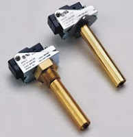
    Fenwal Thermoswitch 20000

    PROBE TYPE, SPST

    Series Features:

  • Individually field adjustable micro-switches
  • One or two micro-switches
  • Specifications:

  • Overlapping ranges from 0° to 300°F (-18° to 148°C)
  • Ratings to 15 A at 120/250 VAC
  • Factory preset temperatures available
  • NEMA 4 enclosure available

  • Agency Approvals:

  • UL, CSA

    Applications:

  • Food service equipment
  • Medical vaporizers
  • Commercial dishwashers


    Based on the differential expansion of metals principle, an increase in temperature causes the stainless steel outer case of the Surface Mounting THERMOSWITCH® controller to expand at a greater rate than the internal bridge assembly.
    Because the case is in direct contact with the heated surface, a temperature change is sensed almost instantaneously.
    Call for availability, most of the part numbers are obsolete as of July 2012.

    Series 30000

    Fenwal Thermoswitch 30000

    SURFACE MOUNT TYPE, SPST

    Click below to buy.

    Series Features:

  • Fully adjustable
  • Narrow temperature differential
  • Compact size
  • Economical
  • Factory preset temperatures
  • NEMA 4 enclosure

  • Specifications:


  • Overlapping ranges from 50° to 600°F (10° to 315°C)
  • 1200 Watt resistive load at 120/240 VAC
  • Minimum contact rating of 100,000 cycle
  • Options:

  • Cross mounting bracket
  • Slotted and extended adjusting screw lengths
  • Factory preset temperature
  • Special range calibration
  • Agency Approvals:

  • UL

    Applications:

  • Plastic laminating presses
  • Food warming trays
  • Popcorn machines
  • Domestic appliances
  • Industrial steam cleaners
  • Anderson-Bolds can supply all of your temperature control needs.


  • Monday, November 15, 2010

    IMS Electric Meters, Integrated Metering Systems


    Integrated Metering Systems, Inexpensive Electric Meters
    IMS - Integrated Metering Systems

    Since 1989 IMS has been manufacturing current transformer (CT) rated electric submeters. These products quantify electrical energy for dozens of applications, including tenant billing, energy management, solar PV production, cost accounting, or any other application where an accurate, easy-to-install electric meter is required.

    Unlike most electric utility meters, our revenue grade CT-rated meters do not plug into a meter socket, so there is no need to re-route power wires. No other electronic meter manufacturer has the confidence and experience to offer a ten-year warranty, and our unique and diverse array of product offerings cover almost any residential, commercial, or industrial application. Our commitment is to 100% customer satisfaction!

    Mini Meters

    Designed for residential applications, these 100A, 200A, and 400A electric submeters are perfect for metering electric consumption or production for nearly any 120V 2-wire or 120/240V 3-wire application. These revenue-grade single phase (120V 2-wire or 120/240V 3-wire) kWh meters make tenant submetering a snap! Available in indoor flush-mount, outdoor surface-mount, or NEMA 4X Multiple Meter Units (MMUs). Also available in UL Listed, NEMA 4X Multiple Meter Units (MMUs), with up to nineteen meters per enclosure.

    Key Features

    • Small size
    • Utility (revenue) grade solid core or easy-to-install split core Current Transformers (CTs)
    • Authorized to apply the UL Mark
    • Approved by Maryland Public Service Commission
    • Approved by California Division of Measurement Standards
    • Approved 2% meter under the California Solar Initiative's PBI program
    • Ten-year warranty

    1000 Series

    This kWh meter with optional demand function has a large LCD display, pulse outputs, and an RS485 serial port for remote monitoring. Available in an indoor steel or outdoor NEMA 4X enclosure (see links at left), which both are UL Listed.

    Models in this series come in the following voltage ratings and configurations:

    • 1 Ph, 2-Wire, 120V
    • 1 Ph, 3-Wire, 120/240V or 2 PH, 3-Wire, 120/208V (same model works with either configuration)
    • 1 Ph, 2-Wire, 277V
    • 2 Ph, 3-Wire, 277/480V

    Key Features

    • Large LCD Display showing kWh and (optionally) instantaneous and peak demand with manual keyed reset
    • Utility (revenue) grade solid core or easy-to-install split core Current Transformers (CTs)
    • Reverse energy LED indicator helps ensure proper installation
    • UL Listed
    • Approved by Maryland Public Service Commission
    • Same low price for indoor steel or outdoor NEMA 4X non-metallic enclosure
    • Approved 2% meter under the California Solar Initiative's PBI program
    • Ten-year warranty

    2000 Series

    Designed for industrial and commercial applications, this UL Listed Three Phase 4-wire revenue grade kilowatt-hour Demand meter is an excellent low-cost option. It features a large LCD display, pulse outputs, an RS-485 serial port, and a ten-year warranty. Same low price for either indoor steel or outdoor NEMA-4X enclosure!

    Key Features

    • Large LCD Display showing kWh and (optionally) instantaneous and peak demand with manual keyed reset
    • Utility (revenue) grade solid core or easy-to-install split core Current Transformers (CTs)
    • Reverse energy LED indicator helps ensure proper installation
    • UL Listed
    • Approved by Maryland Public Service Commission
    • Same low price for indoor steel or outdoor NEMA 4X non-metallic enclosure
    • Approved 2% meter under the California Solar Initiative's PBI program
    • Ten-year warranty

    3000 Series Multi-Function Smart Meter

    (UL Listing Pending. Available Winter 2010)

    The IMS 3000 Series Smart Meter line offers more features and functionality than anything ever manufactured by IMS. Incorporating the latest technology and our decades of energy meter design and manufacturing experience, these products will be suitable for a number of energy monitoring, management, and billing applications, all at a remarkably low introductory price. As always, these products come with the IMS ten-year warranty.

    Standard Features, All Models

    • kWh, maximum demand, and instantaneous power on LCD display and over Modbus serial port
    • Same meter for 3PH 3W Delta or 3PH 4W Y configurations, 208V or 480V
    • Revenue-grade accuracy with solid-core CTs, or easy to install split core CTs
    • Wide operating range with automatic temperature compensation for maximum accuracy (0.5% error max under all conditions with IMS solid core CTs)
    • Large custom LCD display with scroll button
    • 12VDC mechanical counter output
    • Auxiliary 12VDC output @ 200mA for powering wireless AMR devices
    • Two isolated pulse outputs (kWh & 10wh)
    • Low voltage detection
    • Reverse energy indicators (per phase) on display to ensure correct meter installation

    Standard Features on Modbus Serial Port

    • kWh, Max. Demand (kW), Frequency (Hz)
    • Volts, Amps, Watts, VA, and PF per phase
    • Time of Use Metering: Built-in data logger stores kWh, Volts, Amps, and Watts, with date & time stamp from real time clock (65 days of data storage @ 15 minute intervals)

    Optional Features

    • Volts, Amps, Watts, VA, and PF per phase on display
    • Bidirectional Metering (kWh; bidirectional Demand upon request)
    • BACnet interface
    • Ethernet interface (IP addressable)
    • Battery backup for real time clock

    Current Transformers

    Split Core vs. Solid

    Should I order split core or solid core CT's? What's the difference?

    Solid Core

    Solid core Current Transformers (CTs) look like donuts with wires attached. These ring-shaped devices slip over the power lines and measure the electrical current flowing through the line. The CT "secondary" wires connect to the meter, facilitating power and energy calculations.

    Solid core CTs are very accurate (0.3% maximum error), small in size, and inexpensive. However, power must be turned off and the circuit opened, generally at a circuit breaker, so that the solid core CT can be slipped over the power line. After installation the power wire must be reconnected to close the electrical circuit. Installation usually only takes a minute or two per CT.

    Split Core

    Split core CTs can be taken apart, or ‘split' into halves, which negates the need to turn power off and open the circuit during installation. This saves a little installation time, and for critical loads that cannot be switched off, split core CTs are a must. However, split core CTs are more expensive, bulkier, and not as accurate as solid core CTs.


    www.anderson-bolds.com

    216-360-9800

    Friday, September 3, 2010

    Solid State Contactors ~ Gavazzi

    CARLO GAVAZZI
    A u t o m a t i o n C o m p o n e n t s
    Announces new Solid State Contactors and reversing contactors.


    Carlo Gavazzi has announced the launch of the REC Series of 3-phase Solid State Contactors and Reversing Contactors. The REC Series is twenty times more durable than equivalent mechanical contactors and succeeds in handling high frequency switching. The REC Series is comprised of a 3-pole non-reversing version with three switched phases or a 3-pole non-reversing and reversing versions with two switched phases. The first solution eliminates direct connection from the power supply to motor, while the second one maintains the same performance level while providing relevant cost reduction. The REC is mechanically compatible with Carlo Gavazzi’s CGT-22 line of bimetallic overload modules, by means of a plastic adapter.
    In addition to competitive pricing, the REC Series assures substantial savings, as it
    reduces system downtime and maintenance costs. The solid state contactors are provided
    with a 1,600 Vp blocking voltage option that enhances their surge current ratings.
    The REC Series is cUL listed as a motor starter and complies with the NMFT/NMFT7
    requirements. The main technical features include:


    • REC2 / REC3 – direct starting of
    3-phase motors up to 5Hp at 480VAC
    • REC2R – direct starting and reversing of
    3-phase motors up to 5Hp at 480VAC
    • Full load rating at 40°C / 104°F
    • Instant-on switching
    • Rated operational voltage up to 600VAC
    • AC or DC control options
    • Mechanical contactor resemblance with
    covered heat sink
    • Connects to CGT-22 overload module
    • Control status LED indication
    • DIN-rail or panel mounting
    • cULus listed, CE and RoHS compliant


    REC is an electronic contactor intended to replace the traditional mechanical counterpart used to switch three phase motors. The range includes 2 and 3 phase switching versions up to 4kW and 600Vrms.
    Options with high surge current and I²t for fusing purposes are also available. The relay switches instantaneously upon application of the control voltage to emulate mechanical relay operation. A covered heatsink resolves any issues with regards to cables running close to the heatsink and eliminates the need for protective earth cabling. The product can be mounted on DIN-rail or on a panel. Note:
    Specifications stated at 25°C unless specified.


    The solid state contactors are available from Carlo Gavazzi’s North American authorized stocking distributor Anderson-Bolds.

    Tuesday, August 31, 2010

    Watlow Temperature Controls ~ EZ-Zone


    Watlow is standardizing on their EZ Zone controllers, the newest and very highly capable temperature / process controllers on the market. All the controllers share the same base chip/board so can talk to each other and are programmed in very similar fashion.


    Watlow's temperature and process controllers offer easy-to-use, accurate and reliable solutions for applications requiring single and multiple loops of control.

    Temperature and process controllers include one or more sensor inputs with open-loop break detection and multiple outputs for control and alarms. Various configurations offer auxiliary analog inputs, automatic tuning, TRU-TUNE®+ adaptive control, and ramp and soak profiling. Output options include analog process, switched DC and mechanical, solid state and no-arc hybrid relays. Other features include countdown timer, user-customizable menu, burst fire output control, failed heater/load detection and NEMA 4X (IP65, IP66).

    EZ-ZONE controllers offer additional features and options including application blocks with timers and counters, on-board data logging, SENSOR GUARD backup to protect loads should a sensor fail, AUTO CLONE™ automatic configuration backup and restore, standard bus communications, wide ambient-temperature operating range, Class I, div 2 rating, SD card expandable memory, USB connectivity and free configuration software.

    The EZ-ZONE® PM panel mount controller from Watlow®
    offers control options to reduce system complexity and the
    cost of thermal loop ownership. You can order the EZ-ZONE
    PM as a PID controller, an over/under limit controller or these
    functions can be combined into an integrated controller. You
    also have the option to integrate a high amperage power
    controller output with a high-performance PID controller and
    an over/under limit controller in one space-saving, panel
    mount package. A number of communication options are
    available to support your connectivity needs.
    Because the EZ-ZONE PM controller is highly scalable, you
    only pay for what you need. This controller is available in 1⁄32,
    1⁄16, 1⁄8 and 1⁄4 DIN panel mount packages. If you are looking for
    a PID controller, an over/under limit controller or an
    integrated controller, the EZ-ZONE PM will make your
    life easier.

    The Watlow EZ-Zone PM express panel mount controller is an industry leading PID controller tht allows for optimal performance utilizing simple contol and menu functionalitywithout complex features. The EZ-Zone PM express is ideally suited for basic applications and usage levels.

    The Watlow EZ-Zone PM express is the next generation of controllers leveraging the strong legacy of Watlow's Series 93, series 935 and series SD controllers where easy to use features are needed for basic applications. It includes one universal input and the option for up to two outputs and is available in 1/32 or 1/16 DIN panel mount packages.

    The EZ-ZONE® RM controller family offers products that
    simplify thermal system management. The EZ-ZONE RM
    family is comprised of six module types: an integrated on
    or off PID control, monitoring and over/under temperature
    limit module, a high-density on or off PID control module,
    a high-density limit only module, an input/output (I/O)
    expansion module, a high-density monitor/scanner module
    and a data logging and field communications access
    module. A system is configured by connecting any
    combination of module types to address specific application
    needs. The EZ-ZONE RM is extremely flexible and scalable
    allowing you to mix and match I/O to configure 1 to 152
    control loops and up to 256 monitor points.


    Please visit our Watlow Web site.

    or call 216-360-9800

    Thursday, July 15, 2010

    Parker valves, 204/209/304/309 Series

    Parker Solenoid Valves

    Parker Fluid Control Division, manufacturers of the Skinner and Gold Ring lines of solenoid valves and the Sinclair Collins line of process control valves, has introduced an integrated coil for its Series 204 and 304 solenoid valves. Featuring easy installation, the integrated coil is the latest in the division's list of flexible production options for these small yet powerful solenoid valves.

    The patent-pending NEMA 4X coil with rotating conduit hub permits easy installation. The valve lines also include interchangeable AC and DC coils as well as a tab coil for flexible production possibilities. Both the Series 204 and 304 also feature a complete line of high-temperature watertight coil designs to meet the most demanding environmental conditions.

    The Series 204 (two-way) and the Series 304 (three-way) are available as normally closed and normally open valves. Maximized flow rates are delivered through orifice sizes ranging from 1/32" to 5/32". Additionally, the valve line is manufactured with 1/8" port size (NPT) connections.

    The new product lines offer a family of direct-acting solenoid valves for air and liquid (including light oil) applications. These valves meet virtually all of today's commercial, industrial, mobile, instrumentation and medical market needs. State-of-the-art performance characteristics ensure a long life and maximized pressure ratings. Economy models are available for less demanding applications.

    The integrated coil has been evaluated by Underwriters Laboratories and complies with the RoHS (Restrictions of Hazardous Substances) standard under the European Directive 2002/95/EC.

    Visit us online at Anderson-Bolds/Parker

    Thursday, July 8, 2010

    TRC High Power GFCI's ~ Ground Fault Circuit Interrupter


    Anderson-Bolds and TRC

    Avoiding electrical accidents and equipment damage are keys to reducing liability and increasing productivity. Minimum ground fault protection can be incorporated into the main power disconnect device and could be considered adequate for the entire system. However, in such a design, any downstream ground fault could trip the main protective device resulting in a complete substation power outage. The NEC’s purpose, in its own words, is “the practical safeguarding of persons and property…but not necessarily efficient, convenient, or …for good service…” (Article 90.1A, B). In other words, system reliability is left to common sense and good engineering design practices. For this reason ground fault protection of the circuit may be highly desirable and recommended for reliable and continuous operation.
    TRC engineers designed the HD-PRO models specifically for high current, rugged environments and these models are field-proven in all kinds of tough applications. The entire HD-PRO family (120V/30A to 600V/80A) is designed to trip within 25 milliseconds after ground fault detection at an adjustable selected trip level of 6, 10 or 30 mA.
    ARC WELDING APPLICATIONS
    Arc welding is described as using a welding power supply to create an electric arc between an electrode and the base material to melt the metals at the welding point. The process of arc welding is widely used because of its low capital and running costs.
    Arc welding can use either direct (DC) or alternating (AC) current as the power source to create the arc. The arc process needs a large amount of current, up to 500A, but at a relatively low arc voltage; 10 to 40V, with a typical high voltage main power supply, and 230 to 400V, that must be reduced. In all manual arc welding operations the main risk is electric shock, most likely from contact with bare live parts of the welding circuit. Appropriate protective clothing and ground fault protection is the first line of defense in the event of an electrical hazard from stray currents. Bad equipment can be replaced in a short time; however, fire and serious injury or death caused by a ground fault could shut down a facility for several days or weeks.
    How to avoid electrical shock: Always use a local ground fault circuit interrupter (GFCI) with welding equipment and, prior to use, always test the GFCI for proper operation. Use well-insulated electrode holders and cables. Make sure welding cables are dry and free of grease and oil. Keep welding cables away from power supply cables. Wear dry hole-free gloves, clothing should also be dry. Insulate welder from the ground by using dry insulation such as rubber mat or dry wood. Ground frames of welding units. Never change electrodes with bare hands or wet gloves.
    Fortunately, ground fault protection is easy to apply if you understand the basics. Simply put, a ground fault occurs when electrical current finds a bridge to ground via worn insulations, conductive dusts, water or other “soft grounds”, instead of the normal path back to its source. More than 80% of short circuits in equipment are ground faults, and 90% of these events are due to insulation deterioration on wires and cables. In cases where workers accidentally bridge power and ground, current in the mA range can send their heart into ventricular fibrillation.
    A GFCI functions by measuring the outgoing amperage to a piece of equipment and comparing it against the return amperage. If a difference (leak) of >5 milliamps occurs (or set higher for certain equipment), the GFCI stops the flow of electricity to protect equipment and workers from potential electrocution.
    Avoiding electrical accidents and equipment damage are keys to reducing liability and increasing productivity. Minimum ground fault protection can be incorporated into the main power disconnect device and could be considered adequate for the entire system. In such a design, however, any downstream ground fault could trip the main protective device resulting in a complete substation power outage. The NEC’s purpose, in its own words, is “the practical safeguarding of persons and property…but not necessarily efficient, convenient, or …for good service…” (Article 90.1A, B). In other words, system reliability is left to common sense and good engineering design practices. For this reason ground fault protection of the circuit may be highly desirable and recommended for reliable and continuous operation.
    Also, in order to comply with OSHA Regulations’ recent change, “construction-like” work using temporary power arrangements which takes place in the nation’s manufacturing plants, refineries, processing facilities and other locations, must be done with workers using GFCI protected equipment.


    Industrial pressure washers are powerful tools used for washing buildings, bricks, floors, storefronts, parking lots, dumpsters,
    bus fleets, machinery, farm equipment, engines and more. From industrial power plants to disaster clean-up you will find all
    types of high end power pressure washers being used for many industrial applications. These machines are sophisticated
    and built with more durable pumps and components then the residential units. They are also used in extreme environmental
    conditions requiring more power; thereby posing a greater safety risk to individuals if not used properly.
    A “Ground Fault” is a dangerous electrical condition where current flows unintentionally
    between a live conductor and ground. A severe or fatal electric shock can occur when a user
    touches the pressure washer if the machine is ungrounded. This could happen if the power
    cord to extension cord connections become wet or a fault exists within the pressure washer’s
    sophisticated electrical system. GFCI’s prevent possible electrocution and equipment damage
    due to electrical malfunction. Once the GFCI trips, the power is interrupted, stopping the
    pressure washer power and making it electrically safe for people and preventing costly
    equipment damage.
    The 1987 edition of the National Electrical Code requires that pressure washers be protected by ground fault interrupters to
    prevent electrocutions. Also, the Underwriters Laboratories revised UL1776 requires the use of GFCI’s for all UL listed
    pressure washers effective as of May 6, 2000.
    Avoiding electrical accidents and equipment damage are keys to reducing liability and increasing productivity. Guidelines for
    electrical safety are:
    Always use and test the ground fault circuit interrupter (circuit breaker or outlet) before using a pressure washer.
    Always plug a properly grounded pressure washer into a properly grounded receptacle.
    Never remove the grounding prong from the pressure washer’s power cord plug or from the extension cord.
    Always have a qualified electrician check the pressure washer for electrical problems after it has tripped a circuit
    breaker.


    Moving large heavy loads is crucial to today's manufacturing and construction industries. Hoists are one of the top

    productivity-enhancing tools found almost anywhere goods are regularly moved, worked on and/or mounted into an
    assembly. Some hoists use chains, ropes, or cable, but regardless, most use A/C motors. A burnt out motor can be replaced
    in a short time, but fire or serious injury or death caused by a ground fault could shut down a facility for several days or

    weeks. Fortunately, ground fault protection is easy to apply if you understand the basics.
    A ground fault occurs when electrical current finds a bridge to ground via worn insulations,
    conductive dusts, water or other “soft grounds” instead of the normal path back to its source.
    More than 80% of short circuits in equipment are ground faults, and 90% of these events are
    due to insulation deterioration on wires and cables. In cases where workers accidentally bridge
    power and ground, current in the mA range can send their hearts into ventricular fibrillation.
    A GFCI (Ground Fault Circuit Interrupter) functions by measuring the outgoing amperage to a
    piece of equipment and comparing it against the return amperage. If a difference (leak) of > 5
    milliamps occurs (or set higher for certain equipment), the GFCI stops the flow of electricity to
    protect equipment and workers from potential electrocution.
    Avoiding electrical accidents and equipment damage are keys to reducing liability and increasing productivity. Minimum

    ground fault protection can be incorporated into the main power disconnect device and could be considered adequate for the
    entire system. In such a design, however, any downstream ground fault could trip the main protective device resulting in a

    complete substation power outage. The NEC’s purpose, in its own words, is “the practical safeguarding of persons and

    property…but not necessarily efficient, convenient, or …for good service…” (Article 90.1A, B). In other words, system
    reliability is left to common sense and good engineering design practices. For this reason ground fault protection of the
    circuit may be highly desirable and recommended for reliable and continuous operation.

    Guidelines for electrical safety are:
    Know where the GFCI is located in the hoist power system. If there is not a GFCI installed, have one installed local

    to the hoist to confirm you have protection.

    Always test the GFCI before using the hoist.
    Always have a qualified electrician check the hoist for electrical problems after it has tripped a GFCI.

    CONVEYORS

    Conveyors are commonly found in factories, industrial facilities, warehouses, distribution centers and in a large number of
    manufacturing workplaces. A top productivity-enhancing tool, conveyor systems are used in almost every manufacturing
    environment where goods are regularly moved from one location to another. Because of this, conveyor injuries in the U.S.
    may cost employers millions of dollars each year; however, with the right processes, design and safety considerations,
    employers can reduce cost and liability.
    Conveyors are often driven by variable speed electric motors integrated (hardwired) into
    complex power systems. As with any electronic equipment they are subject to failure for many
    conveyor location to isolate equipment protection and to test the GFCI prior to equipment use.
    possible reasons. To protect people who use electrically-powered conveyors, each conveyor
    must be equipped with a “Ground Fault Circuit Interrupter” (GFCI) preferably localized at the
    GFCI’s prevent possible electrocution and equipment damage due to electrical malfunction.
    Once the GFCI trips, the power is interrupted, stopping the conveyor system and making it
    electrically safe for people and preventing costly equipment damage.
    Ground fault protection is an important consideration for virtually all electrical equipment. A Ground Fault is a dangerous
    electrical condition where current flows unintentionally between a live conductor and ground. This could happen if the power
    unit or power cables become damaged, wet or a fault exists within the conveyor’ssophisticated electrical system. Avoiding
    electrical accidents and equipment damage are keys to reducing liability and increasing productivity.
    Guidelines for electrical safety are:
    Know where the ground fault circuit interrupter is located in the conveyor power system. If there is not a GFCI
    installed, report this to your safety officer.
    Always test the ground fault circuit interrupter before using the conveyor.
    Always have a qualified electrician check the conveyor for electrical problems after it has tripped a groundfault
    circuit interrupter.


    TRC engineers designed the HD-PRO models specifically for high current, rugged environments and these models are field-proven in all kinds of tough applications. The entire HD-PRO family (120V/30A to 600V/80A) is designed to trip within 25 milliseconds after ground fault detection at an adjustable selected trip level of 6, 10 or 30 mA.
    Before the development of the HD-PRO Series, facilities with high current – high voltage equipment or three phase systems employed expensive ground fault breakers at the source of the branch circuit, or went without ground fault protection, leaving personnel and equipment unprotected.
    Circuit breakers can withstand high current levels but have short mechanical lives and were not designed for switching duty. Localized ground faults, with circuit breakers, either shut down the whole branch circuit or were overloaded because the available devices were not portable and were often too costly.
    The HD-PRO Series utilizes contactors that are fully rated for motor switching demands. In addition to being far less expensive than three phase breakers, the HD-PRO models protect expensive high current – high voltage equipment at the point of use while offering substantial shock protection for personnel.
    TRC is an internationally recognized leader in electrical safety products
    that protect equipment, prevent electrical fires and protect against electrocution and serious injury from electrical shock.
    Add Image